|
Chip Installation Instructions
Motronic M2.1 (Porsche 964 3.6L 89-94)
Before beginning, you will need the following tools:
- An extended 10 mm socket (about 2” long), socket wrench
- Small flathead screwdriver
REMOVING THE DME CONTROL UNIT FROM VEHICLE:
The Motronic DME control unit is a silver metal box approximately 6”x5”x2” located under the left front seat. It has the word ‘MOTRONIC’ either on a decal on top of the box or stamped on the metal cover. Slide the left front seat all the way back, and also upward for electric seats. Remove the floor matt that covers the control unit. Using a 10mm socket and ratchet, remove the four 10mm nuts and washers that fasten the control unit to the floor. The wiring bundle is held in place with a heavy steel strap that is also held down by a 10mm washer and nut. Lift the unit up and off the studs.
DISCONNECT WIRING PLUG:
Holding the Motronic box in one hand, flip back the steel-retaining tab that holds the electrical connector. Disconnect the box from the wiring plug by rotating the box out so that it pivots away from the retaining tab. When reinstalling, remember that the plastic hook at the end of the connector is installed first.
OPENING THE CONTROL UNIT:
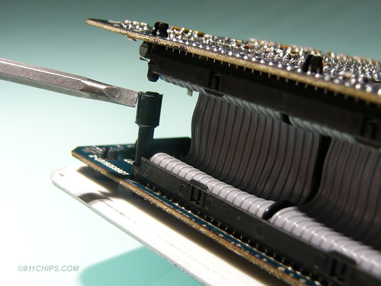
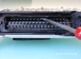
At your workbench, using a small screwdriver, straighten the ten metal tabs on the bottom of the box; remove the cover along with the white plastic insulating sheet and set them aside. At the front of the board is the wiring harness connector block, and at the rear is a wire ribbon cable. The boards are held together by two plastic male/female posts at each end of the wire ribbon cable, which unsnap. The best way to separate these posts is to place a small flathead screwdriver in the slit on the female post as shown by the screwdriver tip below and twist while gently pulling the boards apart. You may have to use some force to separate the two plastic posts, and it is best to pull on the bracket between the plastic posts. Do not pull at the corners of the circuit board or you could flex and break it!
 |
 |
 |
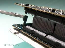
unsnap posts apart |
|
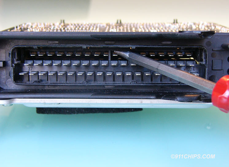
bend both latches inward |
Here is the most difficult step. Within the DME connector plug you will find two plastic latches inside at each end. (see diagram below) To release the latches, take a small pocket screwdriver and insert in the gap between the latch and the plug housing and bend the tab inwards while lifting the board up at the ribbon connector. The upward pressure on the board should keep the latches from relatching when the screwdriver is removed. Release the latch at the other side also.
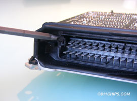
With both latches released, use a screwdriver to press down gently on the upper board as shown below to release the board from the connector plug and allow it to pop out. The upper circuit board can be lifted up at the ribbon connector side and slid out of the plug housing. Gently flip and open the two boards like a book and lay them flat.
 |
|
 |
then push upper board down and out |
|
flip upper board open like a book |
Locate the memory chip on the board that you just unfolded. It will be raised off the board a bit more than the other chips, and has a plastic “H” shaped retaining clip covering it, locking it into the socket. Use a small screwdriver and insert into one of the small slots in the plastic clip to pop that side up. Do the same for the other slot and set the retaining clip aside. If your car has the stock factory chip currently installed, it will have a silver foil sticker on it with a sequence of numbers going something like 126735xxxx.
CHIP REMOVAL:
Before removing the chip, observe its orientation by locating the small notch at the end of the chip. Your performance chip must be installed with its notch facing in the same direction as the original one was. To remove the chip, slide a small screwdriver under the chip and carefully pry upwards, alternating ends frequently to avoid bending or damaging the pins. (CAUTION: MAKE SURE YOU ARE NOT PRYING UP ON THE CHIP SOCKET WHICH IS SOLDERED TO THE CIRCUIT BOARD) As you handle the chip, try to handle it by the black body, and not the metal pins. Place the chip you just removed on the metal cover to protect it from possible static damage.
Install the performance chip by again noting the orientation of the small notch on the end of the chip, and installing it in the same direction of the original chip. There is also a small notch on the chip socket illustrating the correct orientation. If the chip is installed backwards, damage to the control unit could result. Install one row of pins in the socket, and push gently on the other side of the chip until the other row of pins lines up with the socket. Press down and full secure the chip, double-checking that all pins are properly seated. Reinstall the plastic retaining clip, slide the top board back into the connector block, line up the two boards, and then press down on the top board until the two plastic posts snap together. Check that the board's connector pins are properly repositioned in the DME connector plug and that the two latches are properly reseated on each side. Replace the cover and reinstall the control unit.
|